Tel
+86 13145816559

Product Description:
This product integrates a controlled reception pattern array antenna (CPRA) and a digital antenna control unit (DACU) and a GNSS receiver internally.
The CPRA antenna can receive 8 B1/L1/E1 & G1 frequency signals for anti-jamming processing, the signal processed by anti-jamming units combined with the amplified L2/G2/B3 signal then output. This series of anti-jamming GNSS receiver has the function of resisting jamming from 7 B1/L1/E1/G1 frequency and positioning.
Product Usage:
It delivers high-sensitivity and high-precision positioning capabilities, with a design that balances robustness in dynamic environments and anti-jamming performance in complex electromagnetic environments, and offers anti-spoofing capability as an option.
Main Function:
1. Receive satellite signals from GPS-L1, BDS-B1,GLONASS G1 and Galileo-E1.
2. It can reject various types of anti-jamming such as wideband, narrowband, sweep frequency , pulse, and composite jamming, etc.
Electrical Specifications
Receiving Frequency: BDS B1, GPS L1, GLONASS G1, GALILEO E1
Anti-Jam Frequency Point: BDS B1, GPS L1, GLONASS G1, GALILEO E1
Anti-Jam Ability: Single-jam ≥ 120dB, triple-jam ≥ 110dB, seven-jam ≥ 100dB
Numbers of Simultaneous Nulling Directions : 7
Cold Start: ≤45s
Hot Start: ≤10s
Re-acquisition Time: ≤3s
Positioning Accuracy: H: ≤10m (RMS) V:≤10m (RMS)
Velocity Accuracy: <0.2m/s (RMS)
Status 1: velocity≤515m/s, acceleration≤4g
Status 2: velocity≤1000m/s, acceleration≤10g/s,
jerk≤3g/s (optional)
Anti-Spoofing: Optional
Protocols: RTCM2.X; RTCM3.X; NMEA-0183(default)
Voltage: +9~32 VDC
Power Consumption: ≤18W
Mechanical Specifications
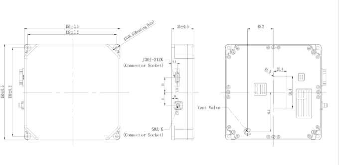
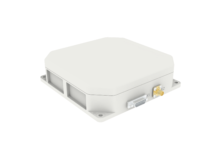
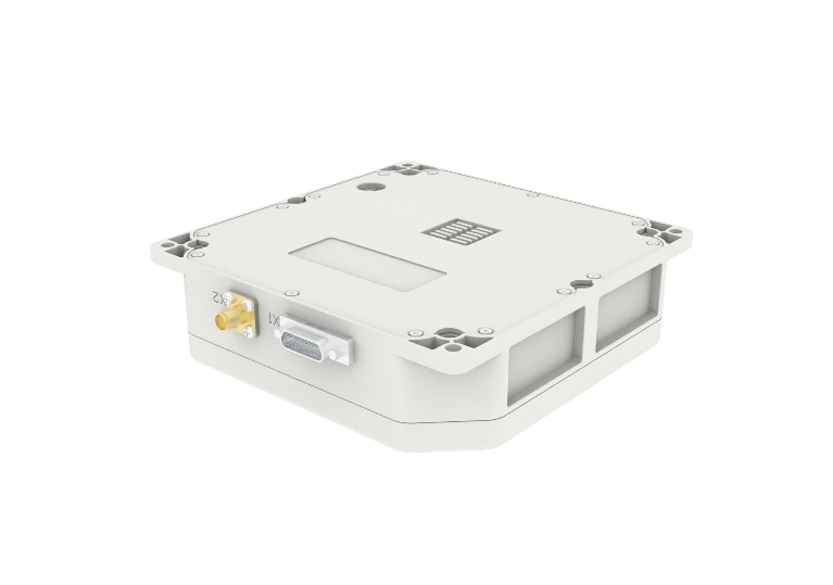
Output Connector: SMA-K (RF)/J30J-21ZK (Data interface)
Dimension: 150×150×35 mm
Weight: ≤750g
Operating Temperature: -40℃~85℃
Storage Temperature: -55℃~85℃
Interface Definition
Data Interface
The connector model for the digital control interface is J30J-21ZK, which provides power. The interface definition is as follows:
No. | Name | Description |
1 | VCC | Power input |
2 | VCC | Power input |
3 | VCC | Power input |
4 | GND | GND |
5 | GND | GND |
6 | GND | GND |
7 | RS232-RX1 | UART1 RX |
8 | RS232-TX1 | UART1 TX |
9 | GND | DGND |
10 | RS485-A2 | UART2 RS485 A |
11 | RS485-B2 | UART2 RS485 B |
12 | NC | NC |
13 | NC | NC |
14 | RS232-RX3 | UART3 RX |
15 | RS232-TX3 | UART3 TX |
16 | NC | NC |
17 | RS485-A4 | UART4 RS485 A |
18 | RS485-B4 | UART4 RS485 B |
19 | NC | NC |
20 | NC | NC |
21 | PPS | PPS |
RF Coneector
The connector model of the RF interface is SMA-K, which only outputs RF signals to the receiver, and the receiver cannot power the antenna through this RF interface.
Diagram