Tel
+86 13924628001


Product Description:
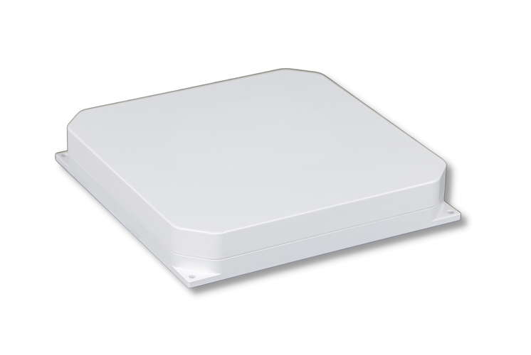
Ø The antenna array consists of 4 BDS B1, GPS L1, GLONASS L1 anti-jam units.
Ø The amplifier circuit has high out-of-band rejection and high linearity, ensuring that it can still work normally in the presence of strong jamming signals.
Ø Built-in voltage regulator circuit, can work normally in a wide input voltage range.
Main Function:
1. Receive satellite signals from GPS-L1, BDS-B1, Glonass-L1, and Galileo-E1.
2. It can reject various types of broadband and narrowband jamming such as harmonics, frequency sweeps, pulses, white noise, frequency modulation, amplitude modulation, and phase modulation for the GPS-L1, BDS-B1, and Glonass-L1 frequency bands.
1. It has the functions of working parameter configuration, query and retention.
2. Equipped with software online upgrade function.
Electrical Specifications
Frequency Range: 1559-1610 MHz
Polarization: RHCP
Gain: Max≥2.5dBi
Axial Ratio: ≤3.0 dB (Elevation angle 90°)
Antenna Unit Isolation: ≥15dB
LNA Gain: 20±2dB
Input VSWR: ≤2
Output VSWR: ≤2
Noise Figure: ≤2 dB
Voltage: 5 VDC
Supply Voltage: RF interface core wire feed, 3.3~5.2 V
Working Current: <50 mA
OIP3: ≥22dBm
Out-of-band Rejection: ≥45@1584±100MHz
Electrical Specifications
Receiving Frequency: 1559-1610 MHz
Anti-Jam Frequency Point: 1601-1575 MHz
Anti-Jam Ability: Single jam ≥ 100dB, triple jam ≥ 85dB
Gain: ≥3dB (Elevation angle 90°)
Signal Output Power: ≤-55dBm
Cold Start: ≤40S
Positioning Accuracy: ≤10m1σ
Speed Survey Accuracy: ≤0.2m/s (Horizontal) , ≤0.3m/s (Elevation) 1σ
Maximum Speed: ≤1100m/s
Maximum Acceleration: ≤15g
Jerk: ≤3g/s
Impedance: 50 ohms
Input Voltage: 18~36V
Power Consumption: ≤15W
Weight: <500g
Operating Temperature: -40℃~ 60℃
Storage Temperature: -55℃~65℃
Interface Definition
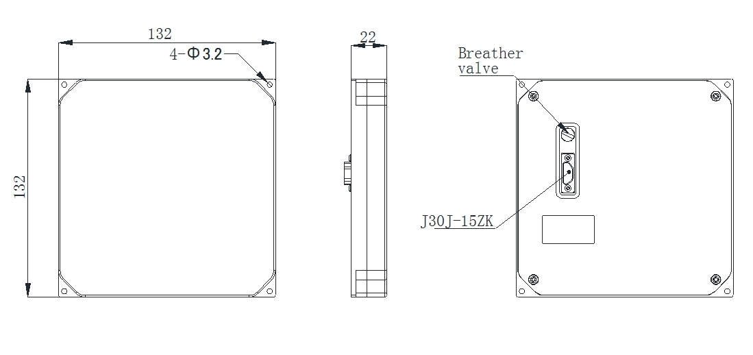
The connector model of the digital communication control interface is J30J-15ZK, which provides power supply and serial communication. The interface definition is as follows:
No. | Name | Description |
1 | VCC IN | 18~36V DC Power Supply |
2 | VCC IN | 18~36V DC Power Supply |
3 | GND | GND |
4 | GND | GND |
5 | 422Rx+ | 422 Signal reception+ |
6 | 422Rx- | 422 Signal reception- |
7 | 422-TX+ | 422 Signal transmission+ |
8 | 422-TX- | 422 Signal transmission- |
9 | TTL | +5V |
10 | ||
11 | ||
12 | ||
13 | ||
14 | ||
15 |
Interface Protocol
1.1 Interface definition
a) Physical interface: serial port
b) Electrical level requirements: standard RS422 electrical level
c) Data content: GPS data
d) Protocol format: UBLOX's PVT protocol (only this protocol data will be output after the module is configured, and no other statements will be output) or NMEA 0183 standard protocol
e) Baud rate: 230400
f) Communication frequency: 5HZ
1.2 Protaol Format
Data frame format
Frame header: Consists of two bytes, namely 0xB5 and 0x62
Following the frame header make up by a byte of CLASS ID and MESSAGE ID information.
Message length: Consists of two bytes, indicating the length of the PAYLOAD message sent later, and the byte order is low endian.
PAYLOAD: Output GPS information
Check bit: Two bytes order of checksum, CK_A and CK_B
Data output frame format
UBX-NAV-PVT (0x01 0x07)
Mechanical Specifications
Output Connector: J30J-15ZK
Dimension: 132×132×22 mm
Weight: <500g
Operating Temperature: -40℃~65℃
Storage Temperature: -40℃~70℃
Diagram
